In industrial automation, State Machines are often used to model the behavior of hardware systems.
State machines definition
State machines are made of:
- States: representing that the system is doing something or waiting for something, like an "Idle" state waiting for a button to be pressed, or a "Moving" state when the system is moving.
- Transitions: representing all the possible state changes, like a transition from "Idle" state to "Moving" state.
- Events: representing something that can occur to activate a transition like an event "eMove" that is generated when the "Move" button is pressed on the system that will activate the transition from "Idle" state to "Moving" state. An event can also be triggered by a timer.
- Conditions: preventing the transition from one state to another if the conditions are not met even if the appropriate event is fired, like checking the state of another device represented by another state machine.
- Actions: something to do either when a transition is executed, a state is entered or a state is exited.
State machines are very useful to model complex behaviors and to represent this visually.
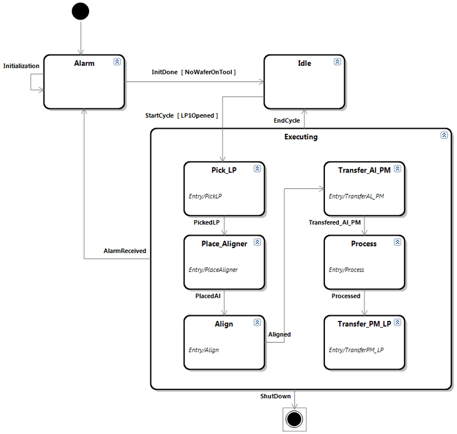
In UML (Unified Modeling Language), class diagrams are often used by software developers to model the code structure and the relations between classes. State diagrams can be used to represent the dynamic behavior. It is based on the mathematical concept of finite state machines with some variation from Harel state charts.
Simple state machines implementation
State machines can be easily implemented in any programming language with a simple switch/case using the current state as the case selector. However this implementation has several drawbacks:
- It requires to maintain separately a drawing of the state machine
- There are often some doubts whether or not the drawing has been updated with the latest patch in the code
- Some developers even do not draw the state machine because they start with a simple state machine with only 3 states but after 6 months the complexity has grown and there is no documentation at all!
- There is no syntax check that verifies that the drawing is correctly representing the implemented state machine
- For complex state machines, switch/case can be error prone (like forgetting a break statement or getting lost in all the states)
Visual State Machines
At Agileo Automation we think, to quote Aristotle, that:
The soul never thinks without an image
As a consequence, we have added State Machines to Visual Studio so that:
- A developer can draw the state and transitions he thinks about concerning a device or a more complex equipment,
- He can share its state machine as an image with its colleagues and its partners to challenge its design and hence to improve it,
- He can get the drawing executable without writing code in a low code approach: What You See Is What You Get (WYSIWYG)
This process is iterative in an agile approach.
A²ECF-Industry and A²ECF-SEMI embed:
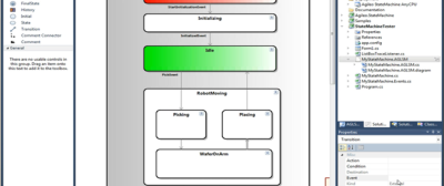
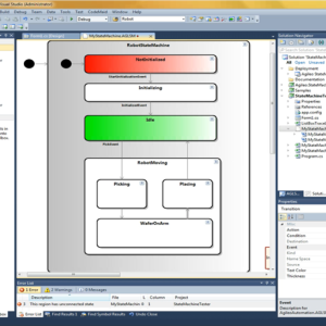
- a Visual State Machine Editor right inside Microsoft Visual Studio ® to design the state machine and make the link with C# code like triggering events or calling actions
- a State Machine Engine to execute the state machine like changing states when an event is fired, checking the conditions and calling actions in the C# code.
See this in action and how it can accelerate your equipment controller development and improve its quality as well as its documentation:
